Insights

Solar Panel Diagram & Single Line Diagram (SLD): Explained with Examples

A permit reviewer usually checks the electrical diagram before anything else. If module counts, inverter ratings or breaker sizes don't match the rest of the plan set, the package comes back with corrections. Two skills help you avoid that delay: knowing how to diagram solar panels clearly, and knowing how to read a solar single line diagram (SLD).

This guide covers:

  • The diagram types in a typical US plan set
  • What an SLD shows and the symbols you'll see
  • Three worked examples
  • The mistakes that most often trigger corrections

Quick Answer

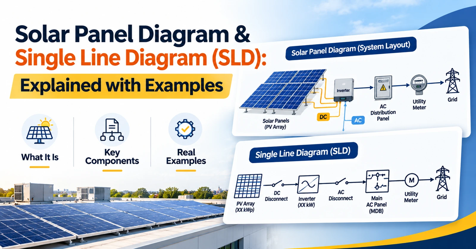
A solar panel diagram shows how a PV system is laid out and connected. In a permit plan set, the most important one is the single line diagram. It traces the electrical path from the modules through the inverter, disconnects and overcurrent protection to the point of interconnection, using one line to represent each circuit. Many AHJs also ask for a site plan, a roof layout and equipment labels. Some also require a three-line diagram.

Types of Solar Panel Diagrams in a Plan Set

DiagramWhat it showsWhen it's used
Site plan / roof layoutArray location, setbacks, equipment placementNearly every permit set
Single line diagram (SLD)Electrical path and ratings, one line per circuitMost permit and interconnection submittals
Three-line diagramEvery conductor (L1, L2, neutral, ground)Commercial or three-phase projects, or when the AHJ or utility asks
Solar panel wiring diagramPhysical string and conductor routingInstallation crews, and sometimes permits
Label and placard sheetRequired warning labels and their locationsMany AHJs, based on NEC labeling rules

A solar panel wiring diagram and an SLD are often confused, but they do different jobs:

  • Wiring diagramShows how conductors physically connect and run in the field. See PV wiring diagrams made simple.
  • SLDShows the electrical relationships and ratings a reviewer needs to verify code compliance.

What a Solar Single Line Diagram Shows

Requirements vary by AHJ and utility, but most residential SLDs include:

  • DC sideModule make, model and quantity. String configuration, temperature-corrected maximum system voltage, and DC conductor and conduit sizes.
  • InverterMake, model and ratings matching the data sheet, plus its listing (commonly UL 1741).
  • Rapid shutdownThe method used to meet NEC 690.12 for PV circuits on buildings. See NEC 690 explained.
  • AC sideThe AC disconnect, conductor sizes and overcurrent protection.
  • InterconnectionMain panel busbar and main breaker ratings, backfed breaker size and connection type. Load-side falls under NEC 705.12, supply-side under 705.11. See the 120% rule.
  • GroundingEquipment grounding conductors and the grounding electrode connection.
  • Notes and title blockThe NEC edition the AHJ has adopted, the project address and the revision date.

An SLD doesn't show conduit routing, roof dimensions or attachment details. Those belong on the site plan and structural sheets.

Common SLD Symbols

Symbol styles vary between designers and software, which is why many AHJs expect a legend on the sheet. Common elements include:

ComponentTypical representation
PV module or stringRectangle with diagonal lines, often labeled with the string count
InverterBox with a DC-to-AC wave symbol
DisconnectOpen switch symbol, labeled DC or AC
Breaker or fuseBreaker arc or fuse symbol with its amp rating
MeterCircle with "M" or "kWh"
GroundStacked horizontal lines

How to Diagram Solar Panels: Three SLD Examples

These examples are simplified illustrations. Real values depend on the equipment data sheets, site temperatures and the code edition in force.

Example 1

String inverter system

Twenty modules in two strings of 10 feed a 7.6 kW single-phase string inverter. The home has a 200 A busbar and a 200 A main breaker. The SLD should show:

  • Each string's temperature-corrected maximum voltage. If one module's Voc is 45 V, a 10-module string is 450 V before cold correction. With a correction of about 12%, it reaches roughly 504 V, under the 600 V limit for one- and two-family dwellings.
  • The DC disconnect and rapid shutdown method.
  • The inverter output. 7,600 W ÷ 240 V is about 31.7 A. 125% of that is about 39.6 A, which calls for a 40 A backfed breaker.
  • The 120% busbar check. 120% of a 200 A busbar is 240 A. The 200 A main plus the 40 A solar breaker equals 240 A. That passes, as long as the solar breaker sits at the opposite end of the busbar from the main.
Quick math: 45 V × 10 × 1.12 ≈ 504 V  |  7,600 W ÷ 240 V ≈ 31.7 A × 1.25 ≈ 39.6 A → 40 A breaker  |  200 A + 40 A = 240 A (120% of 200 A)
Example 2

Microinverter system

The same 20 modules each have a microinverter on the roof, which changes the diagram in a few ways:

  • No high-voltage DC string circuits run from the array, so the DC string calculations drop out.
  • AC branch circuits replace strings. The SLD shows the number of microinverters per branch, which must stay within the manufacturer's limit.
  • Branches usually land in an AC combiner panel before reaching the main panel.
  • Rapid shutdown is typically met at the module level, but the SLD should still state it.
Example 3

PV with an AC-coupled battery

Adding a battery with its own inverter brings in more equipment for the SLD to show:

  • The battery system and its listing (commonly UL 9540).
  • A backup gateway or transfer device that isolates the home from the grid during an outage.
  • A backup loads panel, if only some circuits are backed up.
  • NEC Article 706 references for the energy storage system, plus any utility-specific requirements.

DC-coupled systems look different because the battery shares a hybrid inverter with the array. Either way, the SLD should make the architecture obvious at a glance.

Common SLD Mistakes That Trigger Corrections

Reviewers flag these most often:

  • Equipment on the SLD doesn't match the data sheets or site plan.
  • Module or inverter quantities differ between sheets.
  • Busbar, main breaker and backfed breaker ratings aren't shown separately.
  • The 120% calculation or the supply-side connection details are missing.
  • The rapid shutdown method isn't identified.
  • Conductor sizes appear without the calculation behind them.
  • The NEC edition doesn't match what the AHJ has adopted.
  • There's no legend for the symbols.

Most of these happen when a value is updated on one sheet but not the others. They rarely come from a flaw in the design itself.

A QC pass before submission catches many of them before the reviewer does. That pass should compare the SLD against:

  • The data sheets
  • The site plan
  • The AHJ's requirements

WattMonk builds this step into its solar plan set delivery. An AI-assisted QC check runs against AHJ and utility requirements, and engineers validate the results. Revision support is included if the AHJ still sends comments.

When to Bring In Plan Set Support

Many installers draft simple SLDs in-house. Outside support tends to help with:

  • Battery systems
  • Main panel upgrades
  • Supply-side connections
  • Three-phase or commercial projects
  • Unfamiliar AHJs
  • Repeating correction requests

WattMonk's Solar Plan Set service includes permit drawings, single line and three-line diagrams, structural calculations and equipment specifications. Diagrams are drafted in PlanSetIQ, WattMonk's internal design tool. A sample plan set is available to download from the service page if you want to compare it against your own diagrams.

Want to see what a complete, permit-ready diagram set looks like?

Key Takeaways

A clear solar single line diagram lets a reviewer trace the system from module to meter and confirm each rating. To get there:

  • Keep every value consistent with the data sheets and site plan
  • Show the interconnection math
  • State the rapid shutdown method
  • Check which NEC edition and diagram types your AHJ and utility expect

FAQs

What is a solar single line diagram?

It's a simplified electrical drawing that uses one line per circuit. It shows how a PV system connects from the modules through the inverter, disconnects and overcurrent protection to the utility connection, along with the key ratings.

What's the difference between a single line diagram and a three-line diagram?

A single line diagram represents each circuit with one line. A three-line diagram shows every conductor separately: each phase, the neutral and the ground. Three-line diagrams are more common on commercial and three-phase projects, or when an AHJ or utility asks for one.

Is a solar panel wiring diagram the same as an SLD?

No. A wiring diagram focuses on physical connections and routing for the installation crew. An SLD focuses on the electrical relationships and ratings that reviewers check for code compliance.

Do all AHJs require a single line diagram?

Most US permit and interconnection submittals include one, but the required content varies. Check the AHJ's submittal checklist and the utility's interconnection requirements for each project.

What does a permit reviewer check first on an SLD?

Requirements and review order vary. Reviewers commonly check that equipment matches the data sheets, that string voltage stays within limits, that the interconnection meets NEC 705, and that the rapid shutdown method is identified.

Does a solar SLD need a PE stamp?

It depends on the jurisdiction and the project. Many residential permits don't require an electrical PE stamp, while some AHJs, utilities and most larger commercial projects do. Confirm locally.